the
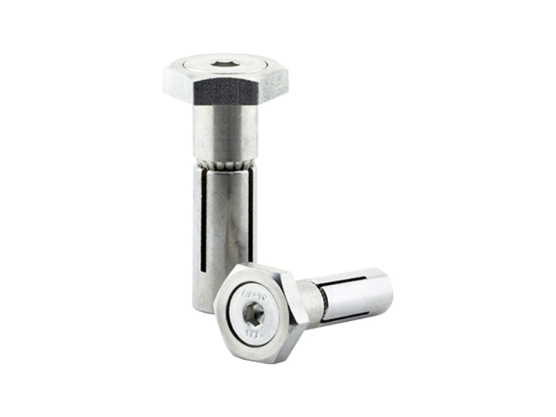
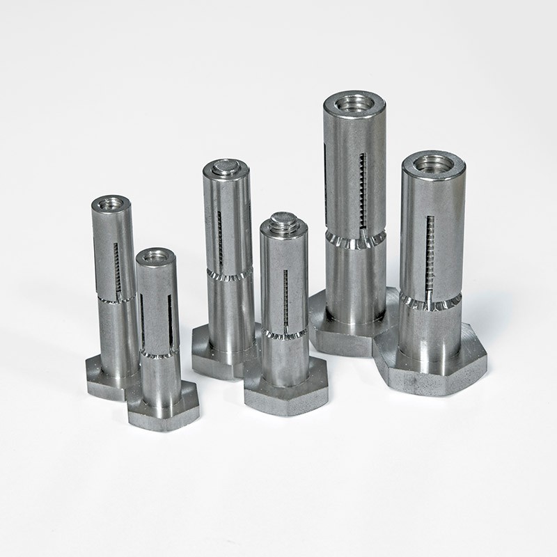
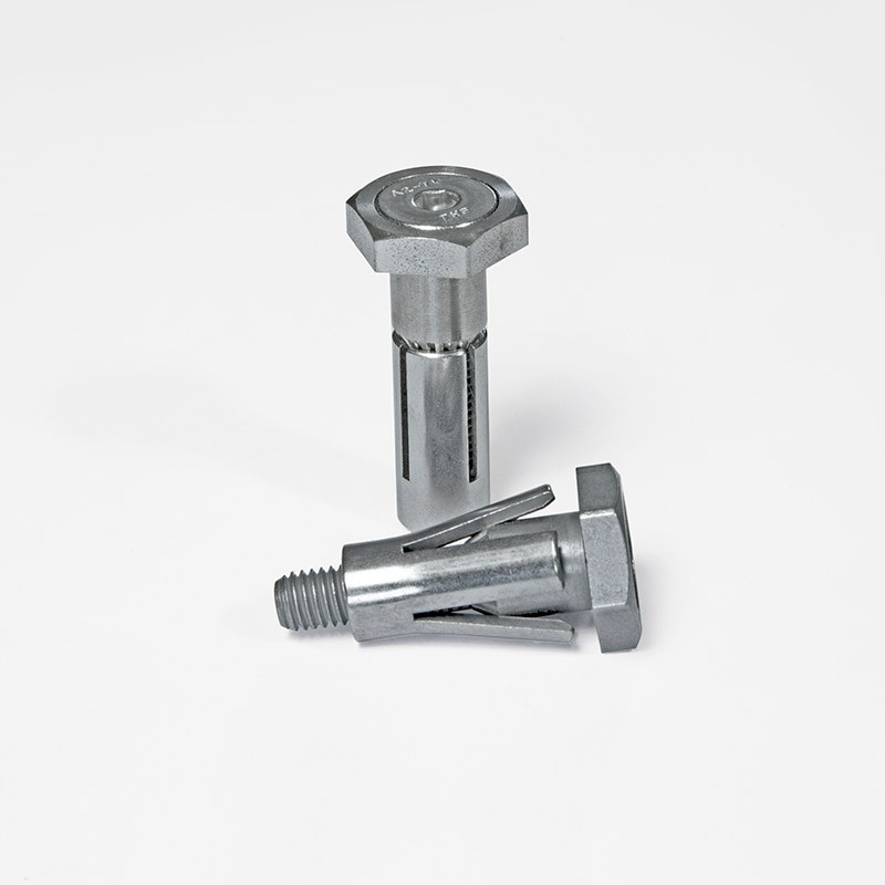
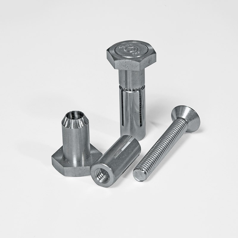
Thin Wall Bolt
Known as the TW Bolt – provides a blind fixing option when working with lightweight steel sheet or cladding material.
Thin Wall Fasteners
TW Bolts offer a mix of a high shear capacity and practical convenience. Once in place, only a low profile head remains visible with no stud.
Thin Wall Bolt Advantages:
- Easy and speedy installation
- No requirement for an oversized hole
- Enhanced durability offered by a zinc electroplate finish
- Brings increases efficiency to any assembly work
Visit our News page to take a look at the innovative applications and new products which we develop in response to our clients’ requirements.If you need Blind Bolt solutions for a planned or ongoing project then please use the contact details below to get in touch with us. We’ll be only too happy just how Blind Bolts could help to save you time and money.
For detailed information on installation or removal, please view our Thin Wall Bolt Installation and removal guide TW Fitting Instructions

Thin Wall Bolt
Technical Data
NOTE: All dimensions are in mm unless stated otherwise.
The Blind Bolt Company reserve the right to change these technical details without notice.
Thin Wall Bolt Product Specification - Zinc Nickel |
||||
| PRODUCT CODE |
HOLE DIAMETER |
DEPTH CLEARANCE |
CLAMPING RANGE |
|
| (mm) | (mm) | MIN (mm) | MAX (mm) | |
| TW5ZF-10 | 8 | 35 | 2 | 10 |
| TW5ZF-16 | 8 | 40 | 8 | 16 |
| TW6ZF-10 | 10 | 35 | 2 | 10 |
| TW6ZF-16 | 10 | 40 | 8 | 16 |
| TW8ZF-10 | 13 | 45 | 2 | 10 |
| TW8ZF-16 | 13 | 50 | 8 | 16 |
Design Resistance for TW Type Blind Bolts Design to BS 5950 - Zinc Nickel |
|||||
| TW Bolt Size |
Set Screw Diameter (mm) |
Collar Outside Diameter (mm) |
Hole Diameter (mm) |
Shear Resistance (kN) |
Tension Resistance (kN) |
| TW5 | 5 | 7.8 | 8 | 13.2 | 4.8 |
| TW6 | 6 | 9.5 | 10 | 19.5 | 14.1 |
| TW8 | 8 | 12.6 | 13 | 34.5 | 25.6 |
Design resistances in shear and tension are presented above. The resistance values may be compared directly with the ultimate loads applied to the fixing.
The bearing resistance may be calculated in accordance with the design standard, based on the external diameter of the collar, as given above.
Fixings subject to combined shear and tension should be verified in accordance with the design standard, using the design resistances presented above.
If tension is applied to a fixing in a relatively thin wall application, the deformation of the connected material should be considered at serviceability (working loads) and at the ultimate limit state, as deformation is likely to be the limiting feature of the connection.
Design Resistance for TW Type Blind Bolts Design to BS EN 1993 - Zinc Nickel |
|||||
| TW Bolt Size |
Set Screw Diameter (mm) |
Collar Outside Diameter (mm) |
Hole Diameter (mm) |
Shear Resistance (kN) |
Tension Resistance (kN) |
| TW5 | 5 | 7.8 | 8 | 15.9 | 4.8 |
| TW6 | 6 | 9.5 | 10 | 23.4 | 10.1 |
| TW8 | 8 | 12.6 | 13 | 41.4 | 18.4 |
Design resistances in shear and tension are presented above. The resistance values may be compared directly with the ultimate loads applied to the fixing.
The bearing resistance may be calculated in accordance with the design standard, based on the external diameter of the collar, as given above.
Fixings subject to combined shear and tension should be verified in accordance with the design standard, using the design resistances presented above.
If tension is applied to a fixing in a relatively thin wall application, the deformation of the connected material should be considered at serviceability (working loads) and at the ultimate limit state, as deformation is likely to be the limiting feature of the connection.
Stainless Steel Thin Wall Bolts
Thin Wall Bolt Product Specification Stainless Steel A2-70 |
||||
| PRODUCT CODE |
HOLE DIAMETER |
DEPTH CLEARANCE |
CLAMPING RANGE |
|
| (mm) | (mm) | MIN (mm) | MAX (mm) | |
| TW5SS-10 | 8 | 35 | 2 | 10 |
| TW5SS-16 | 8 | 40 | 8 | 16 |
| TW6SS-10 | 10 | 35 | 2 | 10 |
| TW6SS-16 | 10 | 40 | 8 | 16 |
| TW8SS-10 | 13 | 45 | 2 | 10 |
| TW8SS-16 | 13 | 50 | 8 | 16 |
Design Resistance for TW Type Blind Bolts Design to BS 5950
|
|||||
| TW Bolt Size |
Set Screw Diameter (mm) |
Collar Outside Diameter (mm) |
Hole Diameter (mm) |
Shear Resistance (kN) |
Tension Resistance (kN) |
| TW5 | 5 | 7.8 | 8 | 11.6 | 7.0 |
| TW6 | 6 | 9.5 | 10 | 17.3 | 9.8 |
| TW8 | 8 | 12.6 | 13 | 30.4 | 17.9 |
Design resistances in shear and tension are presented above. The resistance values may be compared directly with the ultimate loads applied to the fixing.
The bearing resistance may be calculated in accordance with the design standard, based on the external diameter of the collar, as given above.
Blindbolt Fixings subject to combined shear and tension should be verified in accordance with the design standard, using the design resistances presented above.
If tension is applied to a fixing in a relatively thin wall application, the deformation of the connected material should be considered at serviceability (working loads) and at the ultimate limit state, as deformation is likely to be the limiting feature of the connection.
Design Resistance for TW Type Blind Bolts Design to BS En 1993
|
|||||
| TW Bolt Size |
Set Screw Diameter (mm) |
Collar Outside Diameter (mm) |
Hole Diameter (mm) |
Shear Resistance (kN) |
Tension Resistance (kN) |
| TW5 | 5 | 7.8 | 8 | 14.0 | 5.0 |
| TW6 | 6 | 9.5 | 10 | 20.8 | 7.1 |
| TW8 | 8 | 12.6 | 13 | 36.4 | 12.9 |
Design resistances in shear and tension are presented above. The resistance values may be compared directly with the ultimate loads applied to the fixing.
The bearing resistance may be calculated in accordance with the design standard, based on the external diameter of the collar, as given above.
Fixings subject to combined shear and tension should be verified in accordance with the design standard, using the design resistances presented above.
If tension is applied to a fixing in a relatively thin wall application, the deformation of the connected material should be considered at serviceability (working loads) and at the ultimate limit state, as deformation is likely to be the limiting feature of the connection.
Thin Wall Bolt
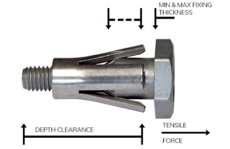
Testing Data Explained
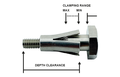
Utilising the unique and innovative TW Bolt system effectively means being fully aware of the way in which the dimensions of the bolt are measured and classified.
These dimensions then play a vital role in meeting the criteria for successful application.
The details of these measurements are set out below and the image above offers pictorial representations.
If you have any more enquiries regarding the fixing terms, contact us using the details given at the bottom of the page of by clicking here to send an email.
However, if there is anything that you are unsure about please feel free to contact us on the number at the top of your screen or send us an e-mail.
Thin Wall Bolt
Fitting Instructions
Installations & Removal Videos
The following videos visually represents the detailed installation of the Thin Wall Bolt.

Thin Wall Bolt
SCI Report
